Volt Dc Motor Wiring Diagram
Volt Dc Motor Wiring Diagram. Architectural wiring diagrams take steps the approximate locations and interconnections of receptacles, lighting, and steadfast electrical facilities in a building. Circuit Diagram and Explanations: Circuit Diagram of this Bidirectional Motor Control Project is shown in image below.

The exclusive Short Circuit and Timed Current Limit (TCL) circuitry prevents motor burnout and demagnetization of PM motors.
DC motors are everywhere, from hobby applications to robotics and industrial areas.

How to Make an Universal DC Motor Speed Controller | Grow Amis
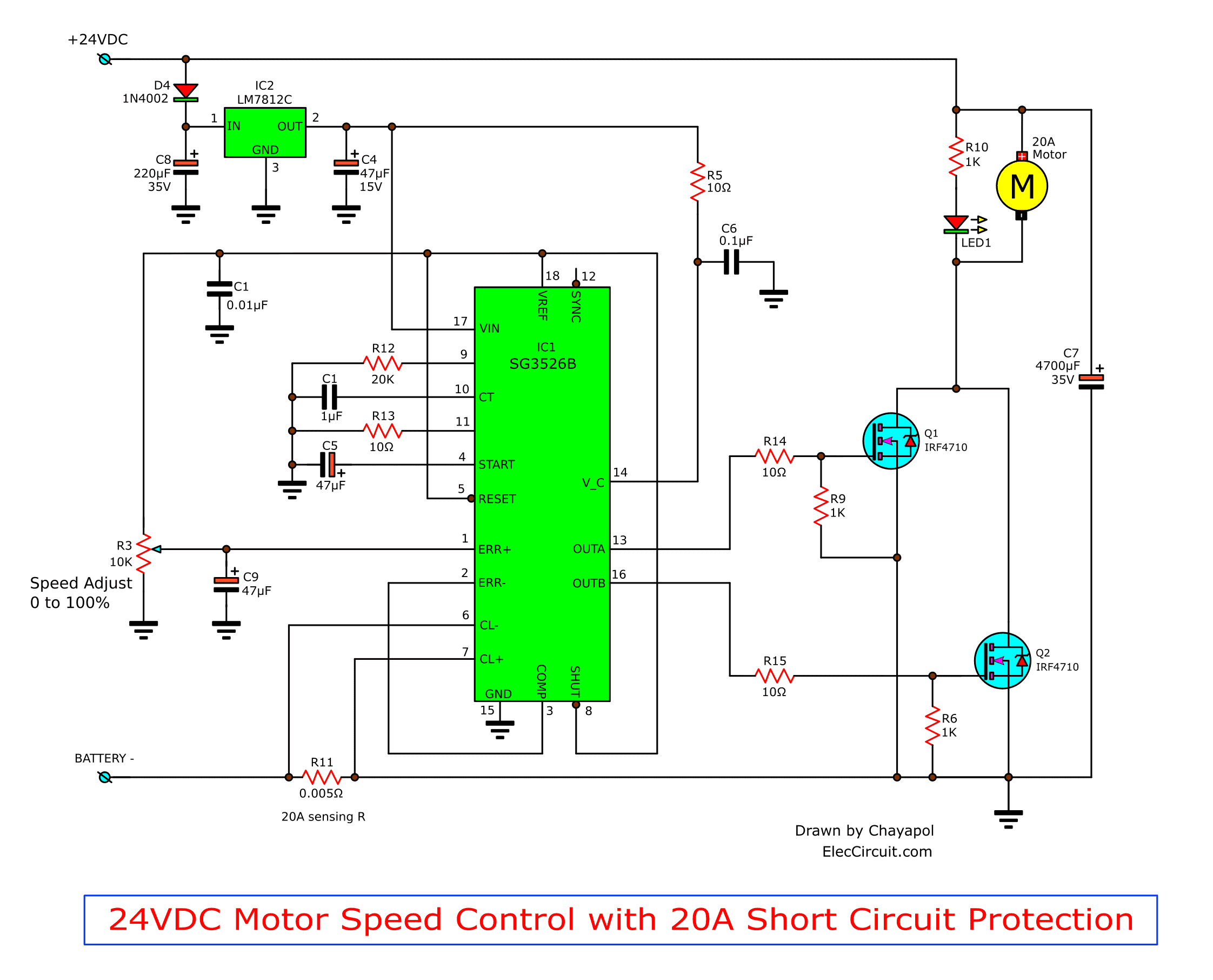
24V DC motor controller with 20A Shot Circuit Protection

DIAGRAM BASED Single Phase 230v Motor Wiring Diagram ...

54537d1340990049-how-reconnect-motor-480-volts-back ...
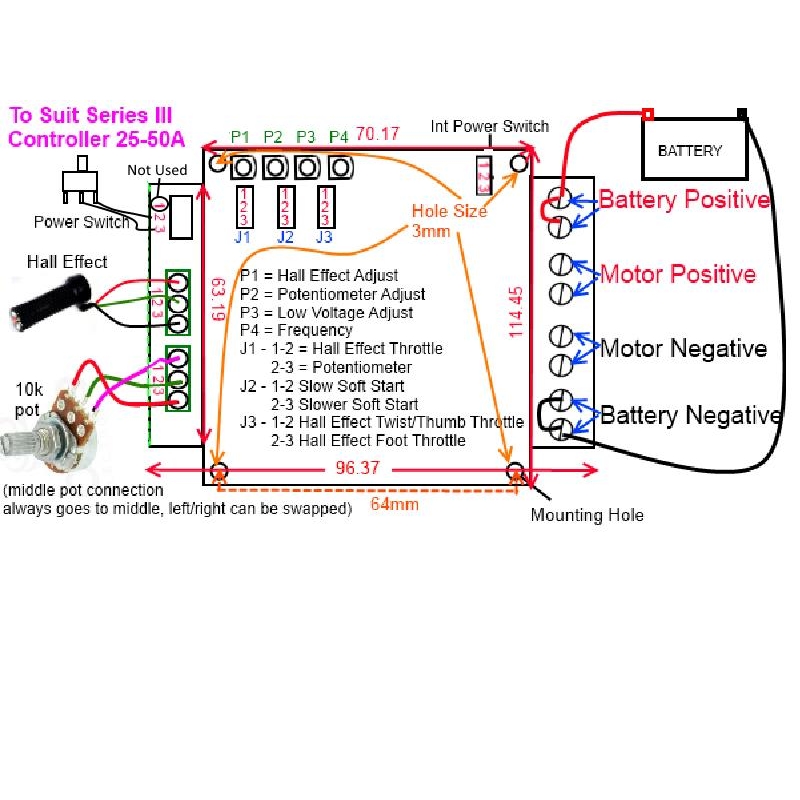
12V-48V DC Motor Speed Controller 25A External Case Model

LM317 Voltage Regulator Circuit Diagram
115 230 Volt Electric Motor Wiring Diagram - Wiring Diagram

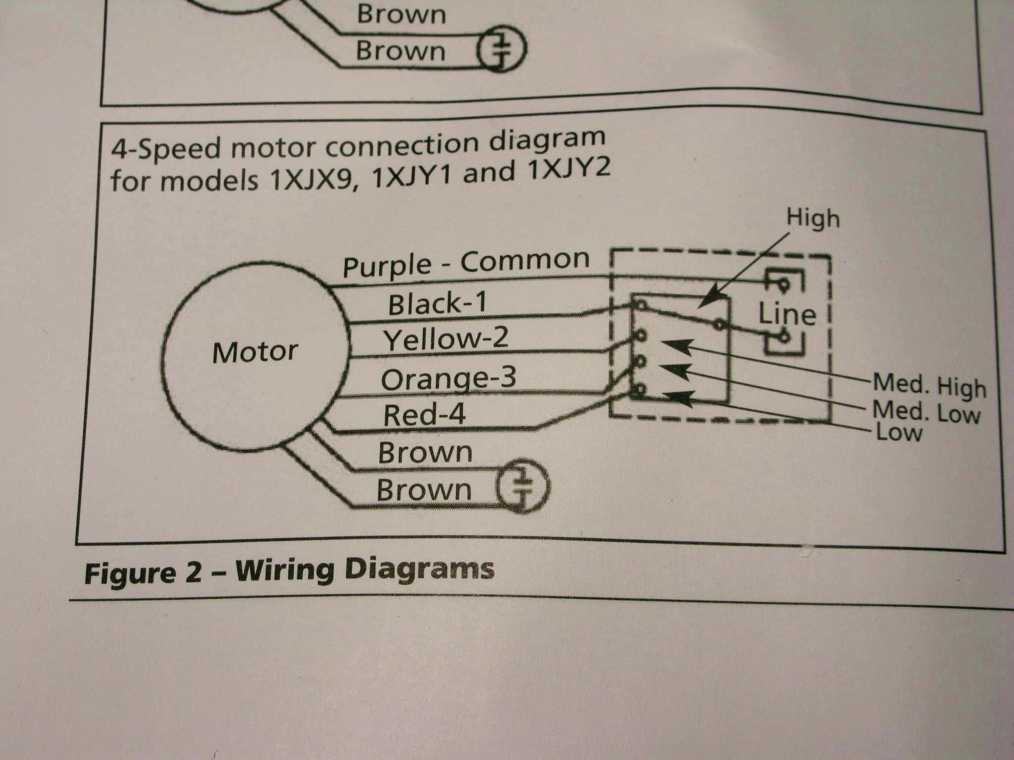
Ac Motor Speed Picture: Century Ac Motor Wiring

120 Volt Electric Motor Wiring Diagram Single Phase ...
Notice the shunt coil is identified as a coil of fine wire with many turns that is connected in parallel (shunt). There are two types of brushless DC motors: sensored and sensorless. I have provided the PWM pulse with a function generator and examined the pulses on the motor wires.

0 Response to "Volt Dc Motor Wiring Diagram"
Posting Komentar