A Esc Wiring Diagram
A Esc Wiring Diagram. Here are pages that will show diagrams for wiring of battery packs very nicely and do any kind of setup The diagrams above show two types of propellers: clockwise (called pushers) and counterclockwise (called pullers). Extending the ESC wires on the motor side of the ESC will not cause destruction of the ESC.
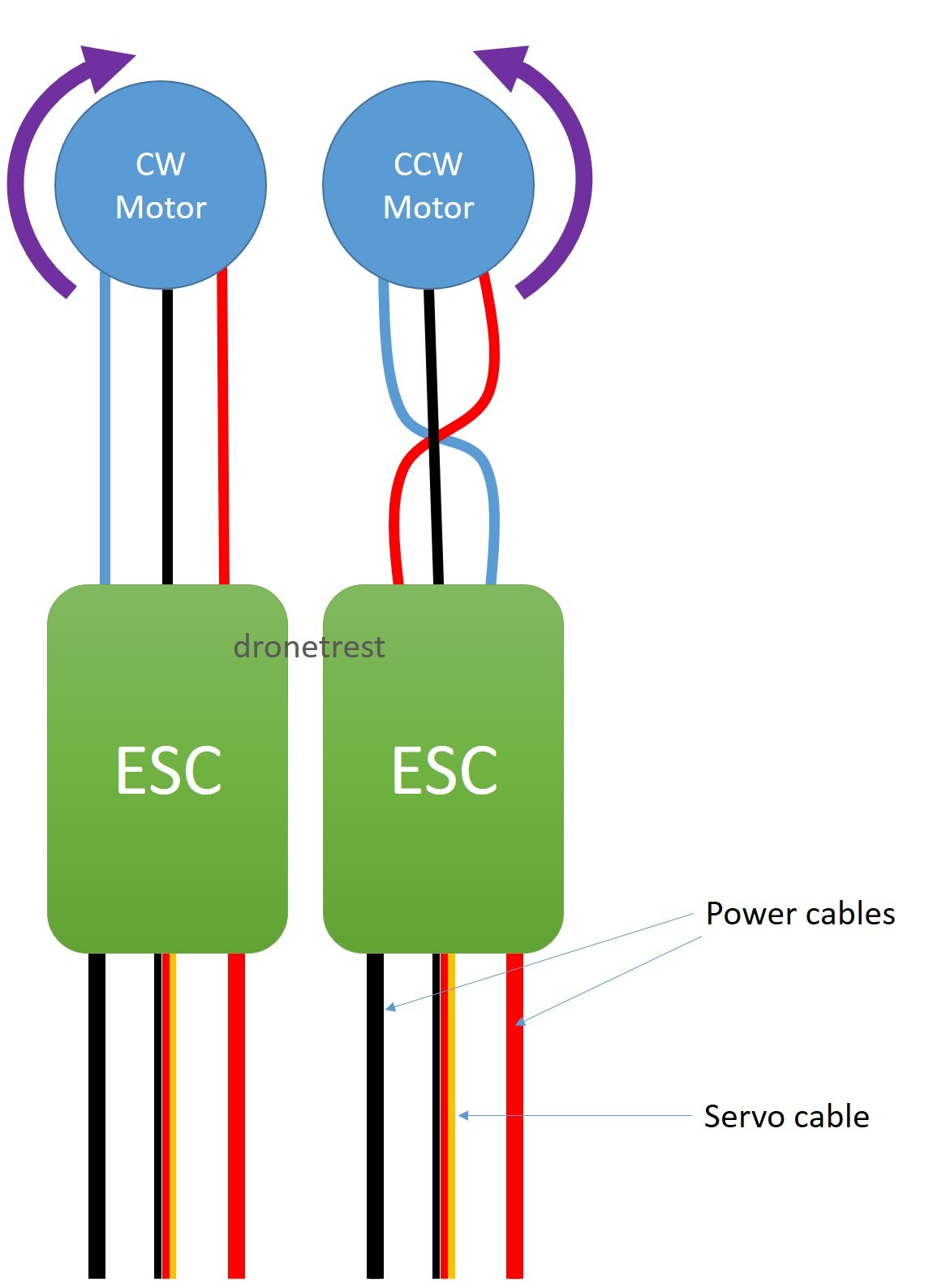
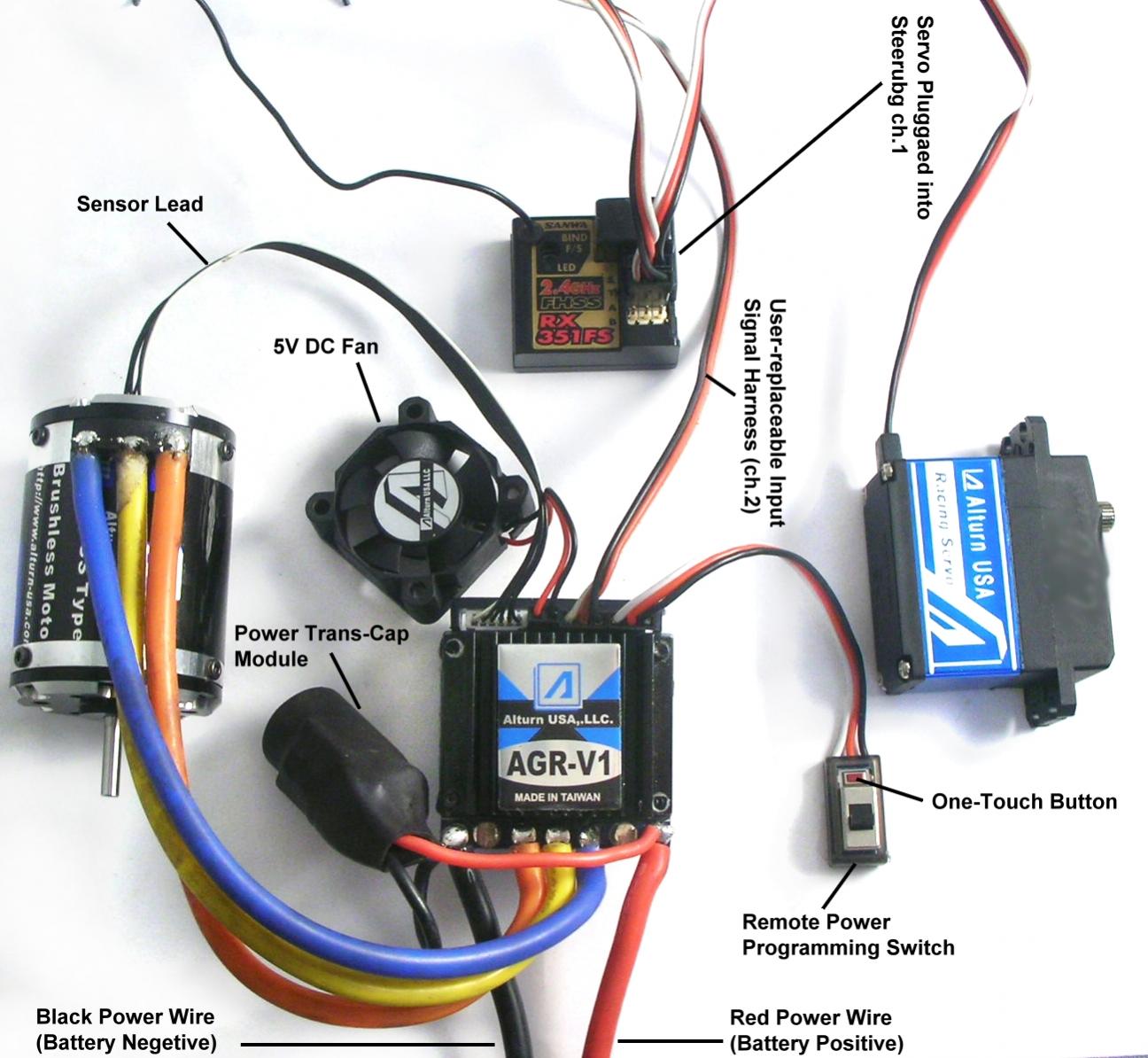
Since wiring connections and terminal markings are shown, this type.
Three wires from the ESC to the motor have no polarity, so you can connect them freely.

Ori32 4in1 Esc Wiring Diagram
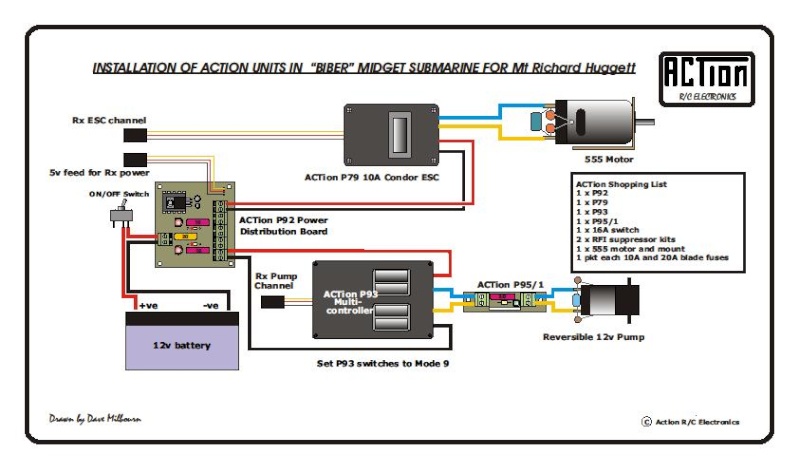
Rc Boat Twin Brushed Motor Twin Esc Wiring Diagram

Racerstar 35a 4 In 1 Esc Wiring Diagram

Drone Esc Wiring Diagram
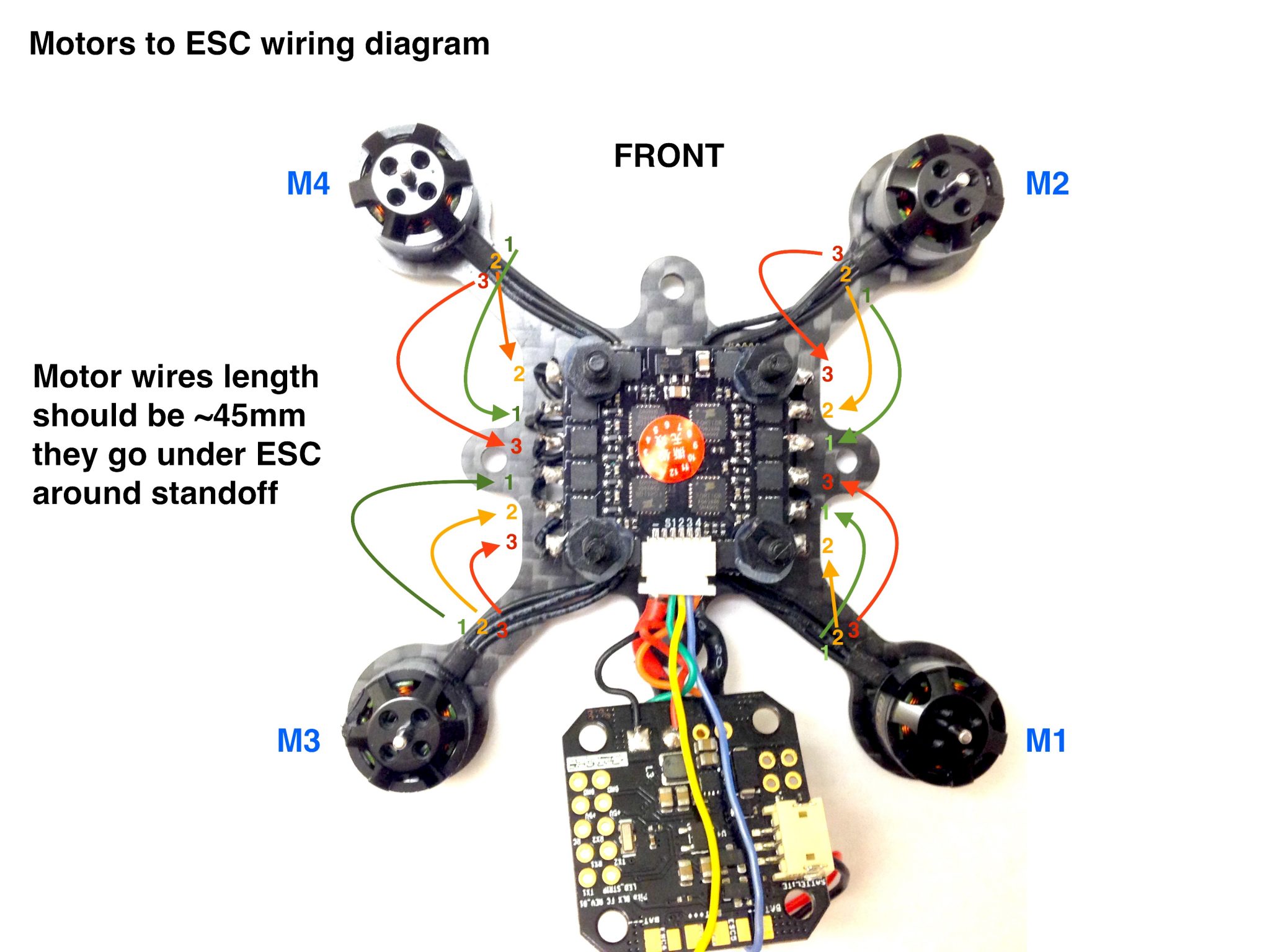
FlexRC Pico Core motors wiring diagram - Flex RC

Micron Wings
20 Best Betaflight F3 Wiring Diagram

Info about Kombini Flight Controller - Oscar Liang
Need help wiring Scanner RC esc to brushless - R/C Tech Forums
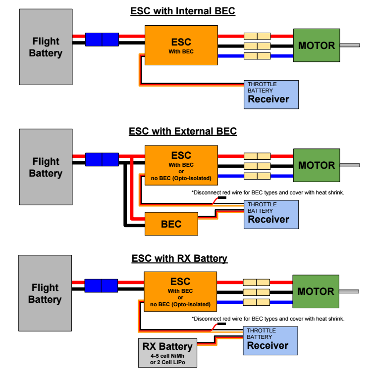
To locate the correct wiring diagram for your vehicle you will need: Make and Model of ABS ECU. On one side the ESC has three wires that control the three phases of the motor and on the other side it has two wires, VCC and GND, for powering. A wiring diagram (also named electrical diagram, elementary diagram, and electronic schematic) is a graphical representation of an electrical circuit.

0 Response to "A Esc Wiring Diagram"
Posting Komentar